
準備が出来たらいよいよVivado ML v2022.2(以下、Vivado、2023.1も操作は同じ)でZynq UltraScale+内部のハード構成を作り、Vitis用にハードウェアプラットフォームとビットストリームを生成します。 2022.2版での参考出来るサイトが見つからず、いくつか試しましたが、.bifファイルのサンプルや、デバイスツリーでの割込の記述などあり、一番成功に近かったMohammadさん(Udemyにも投稿しています)の2020.2を参考にしています。 その為クロックが6個になっています。 しかし2022.2版はvaddのソースも変更されており、自分で変更しなければならないところもあり、2022.2と2023.1版として備忘録を残しています。
Vivado2022.2 (2023.1)インストール
まだの場合は、『組込みLinux Vitis Unified Software Platform 2022.2インストールと起動方法』をご参考ください。(2023.1のインストールも記載しています。)
Ultra96 v2のBDFインストール
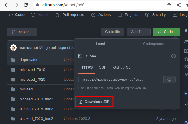
https://github.com/Avnet/bdf に行きzipファイルをダウンロードします。 (BDF: Board Definition File :Ultra96V2のハード構成が入っています。) 『Code』をクリックすると『Donload ZIP』が表示されます。
- zipファイルを展開すると『~/Downloads/bdf-master』ディレクトリが出来ます。
- 『/tools/Xilinx/Vivado/2022.2/data/boards/board_files』ディレクトリを作って、『~/Downloads/bdf-master』ディレクトリの中身を全てコピーします。
$ sudo mkdir /tools/Xilinx/Vivado/2022.2/data/boards/board_files
$ sudo cp -r ~/Downloads/bdf-master/* /tools/Xilinx/Vivado/2022.2/data/boards/board_files
Vivado
ディレクトリ
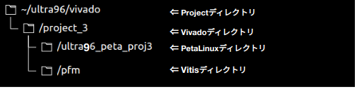
知らない時に作り始めたので、Vitisまで終わったときには、VivadoとPetaLinuxとVitisのプロジェクトディレクトリをこんな風に作ってしまいました。 本来はProjectディレクトリ下にVivadoとPetaLinuxとVitisが並列になっていてもいいのかなと思います。 またディレクトリ名にもVivadoやVitisの文字が入って長さも短い方が良かったですね。
起動
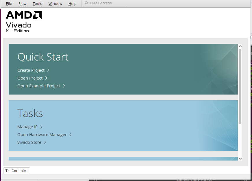
settings64.shとsettings64-Vivado.shを実行してから、ホームディレクトリでvivadoを立ち上げます。 settings64.shとsettings64-Vivado.shの実行は毎起動後に必要です。 『Copyright 1986-2022 Xilinx, Inc …』が表示されて1分後位に、スタート画面が表示され、そこから更に1分ほど経ってVivadoが立ち上がります。
$ source /tools/Xilinx/Vivado/2022.2/settings64.sh
$ source /tools/Xilinx/Vivado/2022.2/.settings64-Vivado.sh
$ cd ~
$ vivado
****** Vivado v2022.2 (64-bit)
  **** SW Build 3671981 on Fri Oct 14 04:59:54 MDT 2022
  **** IP Build 3669848 on Fri Oct 14 08:30:02 MDT 2022
    ** Copyright 1986-2022 Xilinx, Inc. All Rights Reserved.

start_gui

立ち上がったら『Create Project』を選びます。
2023.1ではXilinxのロゴがなくなっていますね。
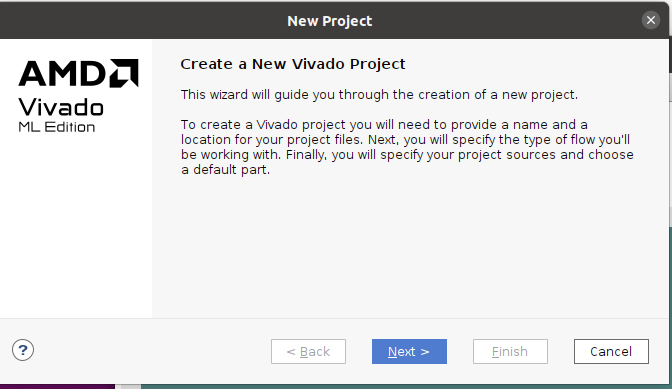
『Next』
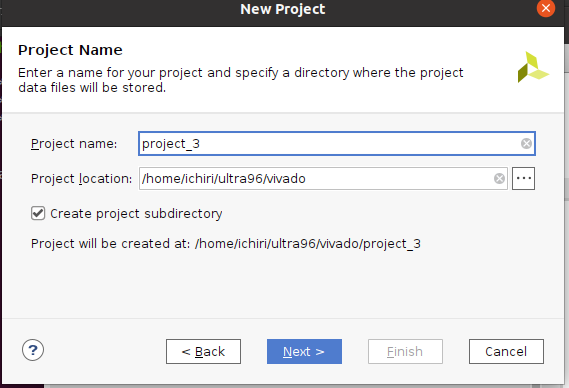
Project nameとProject locationを入力して『Next』。
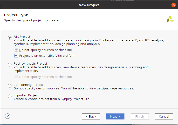
- 『RTL Project』を選択
- 『Do not specify sources at this time』にチェックを入れて
- 『Project is an extensible Vitis platform』にチェックを入れて
- 『Next』
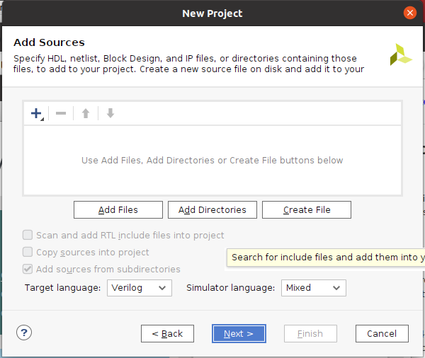
『Next』 (*後からでも追加出来るはずです) この画面は2023.1では表示されませんでした。
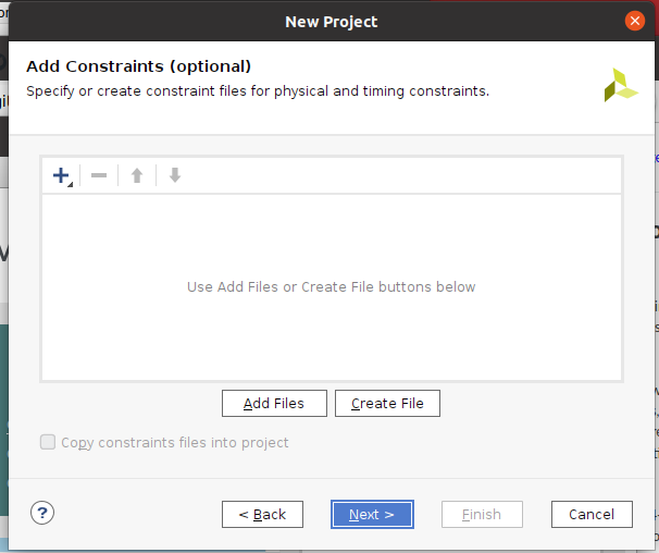
もしAdd Constraintsが表示されたら、何もせず『Next』 (*後からでも追加出来るはずです)この画面は2023.1では表示されませんでした。 Vivadoが立ち上がって、『File』〜『Add Sources』〜『Add or create constraints』で後からいつでも追加できるので、ここではスキップ。 因みに、Constraintsとは、xdc(Xilinx Design Constraint)ファイルの事で、Xilinxの場合、ピン配や設定を記述します。
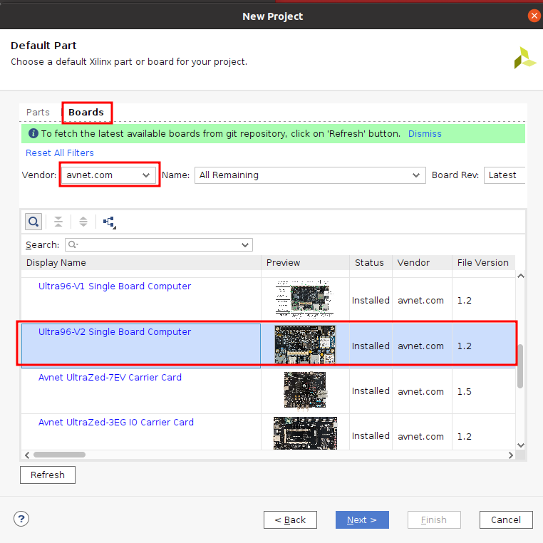
- 『Boards』タブを選んで
- Vendorで『avnet.com』を選んで
- 『Ultra96-V2』を選んで
- 先程、Board Definition Files をコピーしていたので、『Ultra96 V2』が表示されます。
- 『Next』
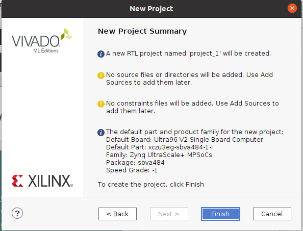
『Finish』 2023.1では、2画面表示されなかったので、黄色の警告2つは表示されませんでした。
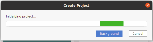
1分ほどかかりました。(*新しいPCでは3秒ほどでした)
こんな画面が出てきました。
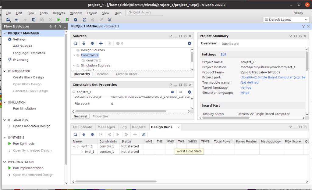
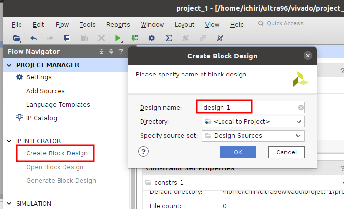
左のFlow Navigator内のIP INTEGRATORの下にある、『Create Block Design』を選び、『Design name』を入力し、『OK』を押します。
*私はDesign nameに『design_ultra96v2』としました。(下の絵から変更しました)
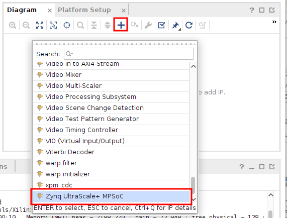
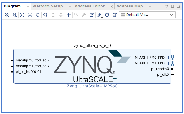
画面右側にDiagram画面が表示されるので『+』を押して、リストから『Zynq UltraScale+ MPSoc』を選択して『ENTER』。
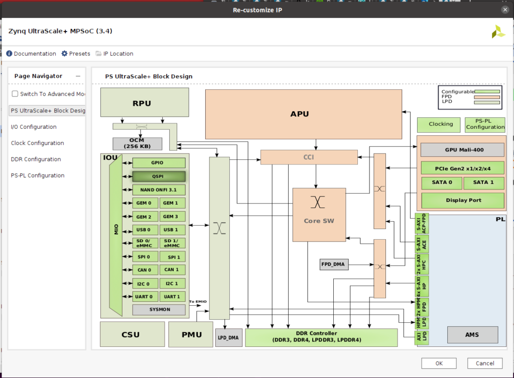
Zynq UltraScale+ブロックが表示されるので、そのブロックをダブルクリックします。
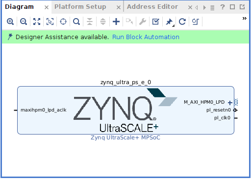
ブロックダイヤグラムが開きますが、何も変更せず『ESC』で抜けます。 この図でわかる通り、周辺は何も接続されていません。
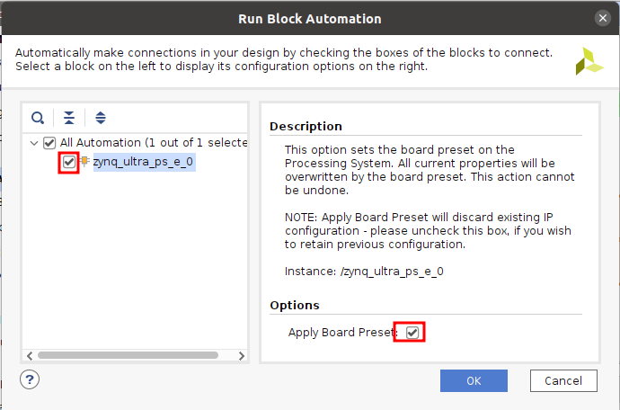
『Run Block Automation』をクリックします。
『Apply Board Presets』にチエックを入れたままで『OK』を押して、Ultra96 v2ボードの周辺とZynq UltraScale+のPS部との自動での接続をします。
見かけは何も変わっていないように見えますが『ZYNQ UltraScale+』のブロックをダブルクリックしてBlock Designを開くと
GPIOやUSBなどに『✔』マークが付いています。 これでUltra96 V2用の接続設定となりました。
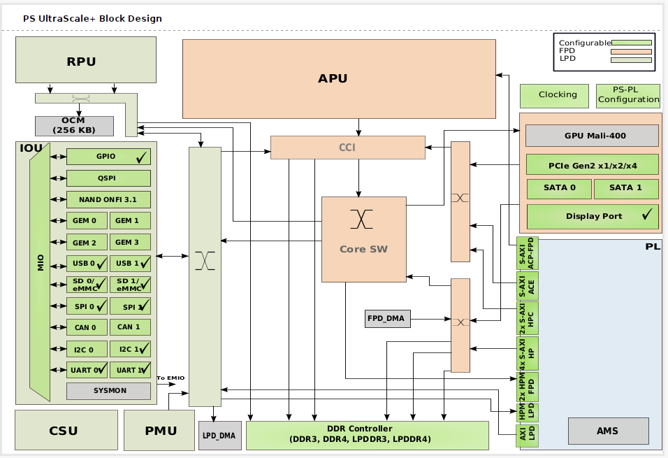
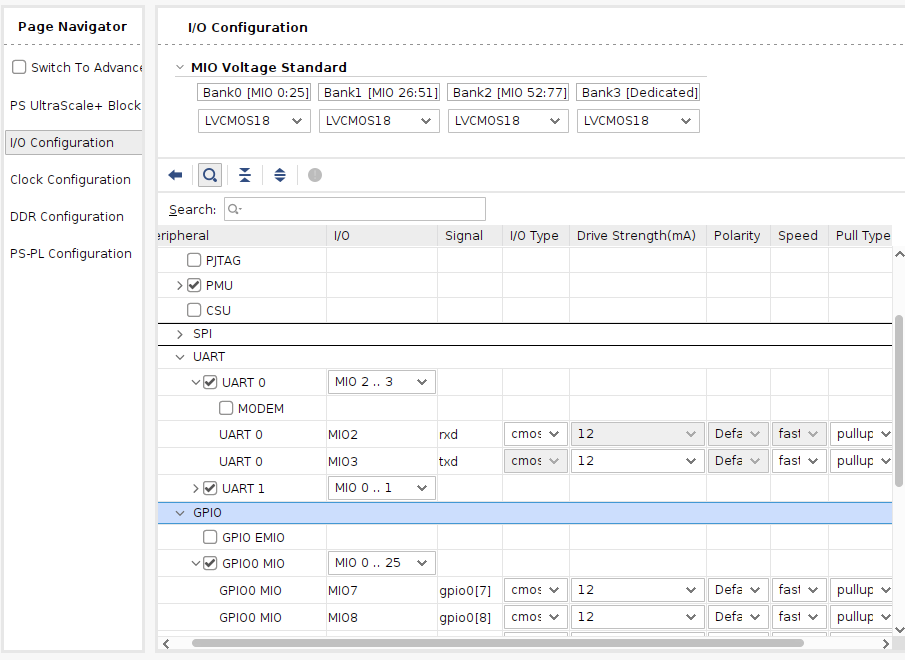
左のPage Navigatorの『I/O Configuration』か、上の図のGPIOをクリックすると、『I/O Configuration』画面が表示されます。 ここで各IOに信号レベル、高速/低速、プルアップ有無などを設定します。 (今回は何もしません)
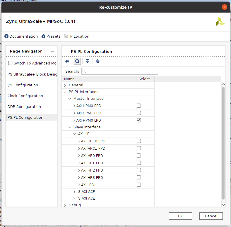
- Page Navigationから『PS-PL Configuration』を選び、
- 『PS-PL interface』を選び
- 『Master Interface』の下の『AXI HPM0 LPD』だけ『✔』を入れて
- 『OK』
clocking wizard
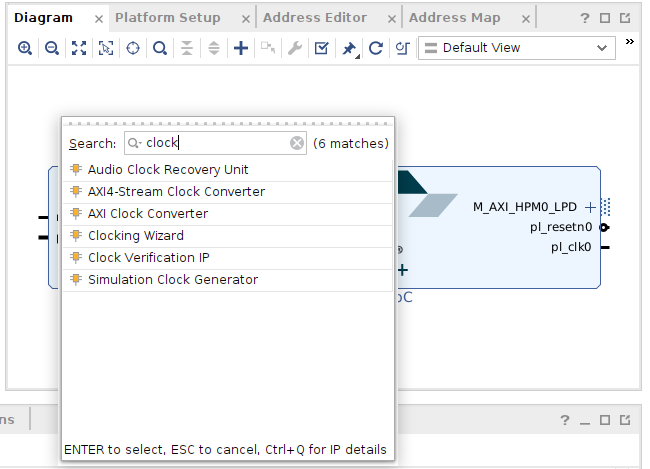
- Diagram Viewの白い部分を右クリックして『Add IP』(『+』をクリックしても同じ)
- 『Clocking Wizard』を選択
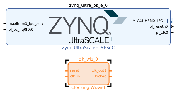
clk_wiz_0ができるので、clk_wiz_0をダブルクリック。
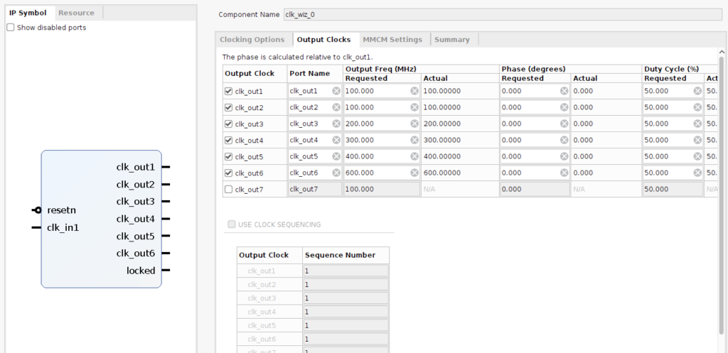
- 『Output Clocks』のタブを選び
- 『Output Clock』の下の『clk_out2』から順番に下にチェックを入れて、下の図のように『Requested』の数値を入れていく。
- 画面をスクロールダウンして『Reset Type』 は『Active Low』にチェックを入れて、
- 『OK』
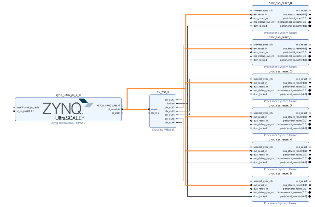
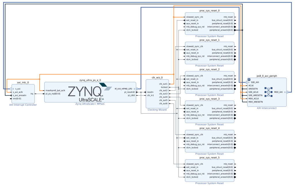
次に『Add IP』から『Processor System Reset』を選んでコピー&ペーストで6個作り以下のように接続
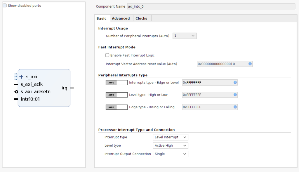
- 『Add IP』から『AXI Interrupt Controller』を選び、
- 画面の下の方の『 Interrupt Output Connection』で『Single』を選んで
- 『OK』
オレンジのように接続して
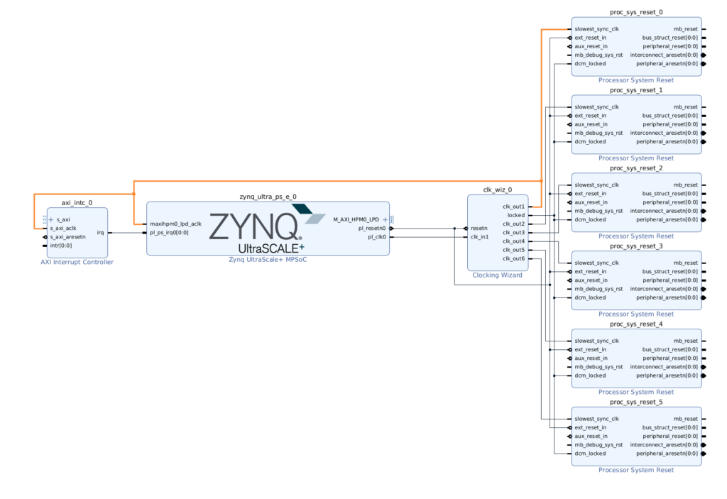
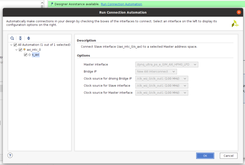
- 画面上の緑部分の『Run Connection Automation』をクリックすると下の画面が表示されるので、
- 『OK』で残りを自動で接続
すると、以下の様に右のAXI Interconnectブロックが現れ自動で接続される。
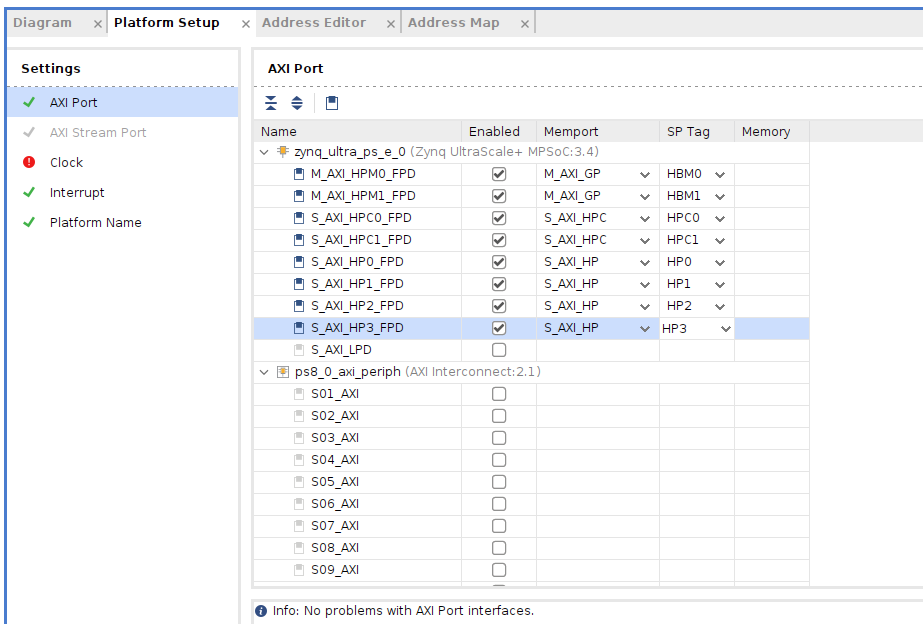
上部の『Platform Setup』タブを選んで、『zynq_ultra_ps_e_0』の下の『AXI Port』を選んで以下の用に設定する。
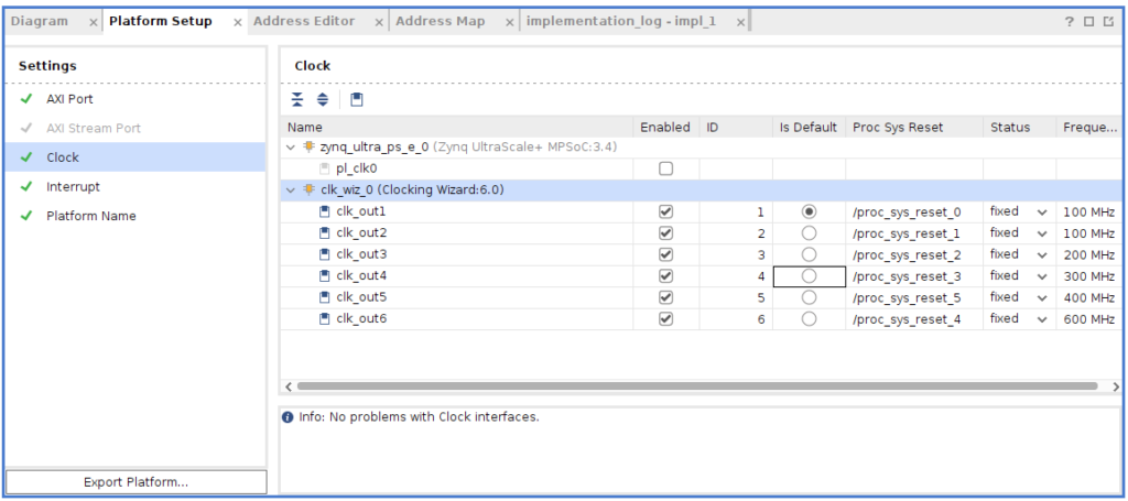
- 同様に『Platform Setup』の下の、『Clock』を選択してい可能の様に設定する。
- 『clk_out1』~『clk_out6』まで『Enabled』のチェックを入れる。
- 『ID0』がないと今後エラーとなるので、『ID』を以下のように『0』からにする。
- 『Is Default』も『ID0』を選択する。
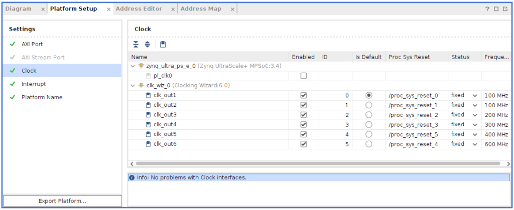
(失敗例)最初は以下のようclk_out1をEnabledにしてなかったら.xsaファイルを生成出来なかった。
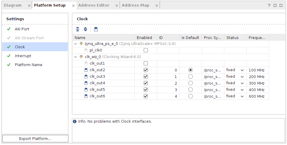
(失敗例)IDが0のClockがなかったら、Platformを作る時に、ERROR: [CFGEN 83-2299] Clock ID 0 must exist. Please correct the targeted platform.となった。
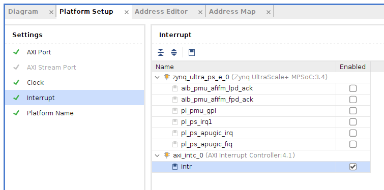
同様に『Platform Setup』の下の、『Interrupt』を選択してい可能の様に設定する。*2023.1では、axi_intc_0は上の方に表示されていました。
左の『Flow Navigator』の下の『PROJECT MANAGER』の下の『Setting』〜『General』で『Project is an extensible Vitis platform』にチェックが入っているか確認。(*最初プロジェクトを作る時チェックを入れたはずですが念の為確認)
Validation(前検証)
Block Designは全てのIPの設定とBlockの接続情報を設定出来ます。 合成には時間がかかり、エラーが出たら時間のロスになります。 なので合成する事前チェックとして『Validation』を実行します。
『Digram』のタブをクリックしてブロック接続図を表示して、白い部分で右クリックして『Validate Design』を選ぶか、『F6』を押します。
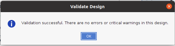
本来はこの様に出るはずですが、
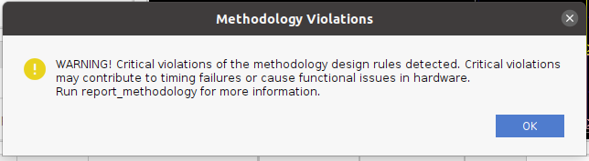
割込コントローラのintr端子が接続されていないので、以下の様なCritiral Warningが表示されましたが、VitisチュートリアルXD098によると、intrは後ほどVitisで接続されるらしいので無視して進みます。『OK』
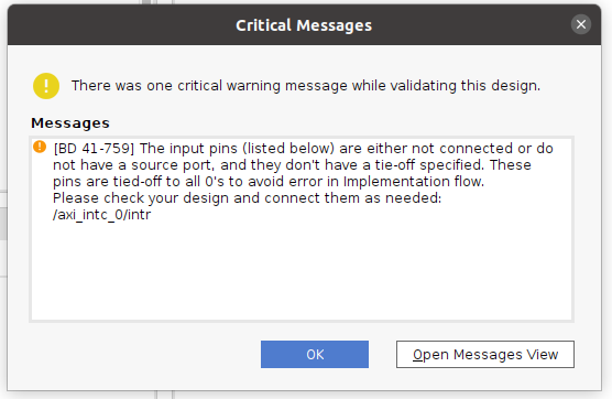
その他にも、proc_sys_reset IPも関して制約が記述されていないので、critical warningが表示されましたが無視して進みます。
Wrapper作成
- Vivadoは合成前にDesign Top(最上位に来るソースファイル?)をHDL(VerilogなどのRTL言語)にする必要があるので、この『Create HDL Wrapper』を実行します。
- 『Block Design View』で『Sources』タブを選ぶ、
- 下の『Hierarchy』を選ぶ
- 『Dsign Sources』の下の『design_ultra96v2.bd』上で右クリック
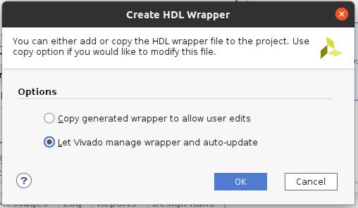
- 『Create HDL Wrapper』を選ぶ
- 『Let Vivado manage wrapper and auto-update』を選んで『OK』
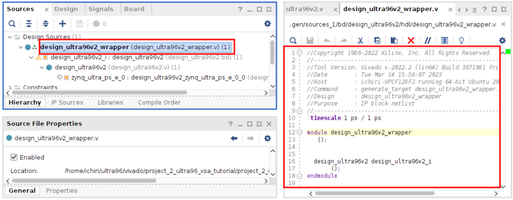
.vファイル(Verilog)が出来ていますね。 上位のファイルが必要なだけなので、Wrapperとしてのカバーだけで中身は何もないですね。 そしてその下に、.bdファイルが瀬尾瀬尾されています。
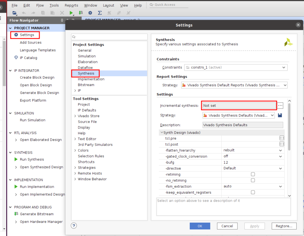
ビルド前の設定 disable incremental synthesis
- これを設定しないと、.xsaファイルに.dcpが含まれてしまう。『.dcp file not found』となりVitisのプラットフォームをビルドできないので設定する。
- 『Incremental synthesis』の『・・・』ボタンを押してダイアログボックを開く
- 『Disable incremental synthesis』を選択して『OK』で閉じるる
- 下の図の様に『Not set』となれば設定できているので『OK』で閉じる
- 『.dcp』はDesign Check Pointの略。
- ビルドには『Synthesis』と『Implementation』と『Bitstream』のビルド工程があり、それぞれ時間がかかるので、多分この機能を『Enable』にしておくと、途中からビルドが出来るのだと思う。 一回もSynthesis指定ない状態で、『Export Platform』をすると、.xsaに.dcpファイルが含まれないと何処かに書かれていたけど、二回目以降に『Export Platform』すると、既に生成されていた.dcpファイルが含まれてしまっていた。なので、どちらもメリットデメリットがあるので、FPGA部を多くプログラムしていないので、.dcpファイルを作らないIncremental SsynthesisをDisableに設定しておく。(詳細は、まだ分っていません。)
- もし、一度でもSynthesisをしてしまってからこの設定にしても、.dcpファイルが出来てしまっているので、.dcpファイルや.dcpファイルが入っていた空のディレクトリを削除してから、再度Synthesisをするとうまく行きました。
Bitstream生成
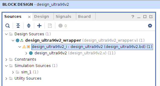
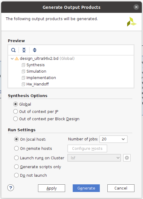
『Sources』で『Design Source』の下の『design_ultra96v2.bd』を右クリックして、『Generate Output Products…』を選択して
- 『Global』を選択して
- 『Generate』を押す。 1~2分ほどで完了して、Warningが表示されるが『OK』を押して次に進む。(新しいPCでは10秒ほどで完了。以下の図は新しいPCで20スレッド。)
- 次に、左側の『Flow Navigator』の下の『PROGRAM AND DEBUG』の『Synthesis』をクリック
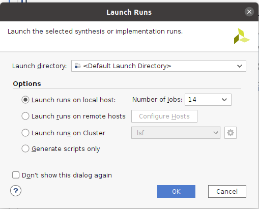
- 『Launch runs on local host』で『OK』
- 下の図は新しいPCで14スレッドで実行した例。(20スレッドで38秒かかりました)

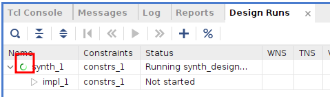
完了のダイアログボックスが表示されないので、終わったのか実行中かわかりにくいです。 そんな時『Design Runs』のタブを開くとこの様にくるくる回っている間は実行中と分かります。
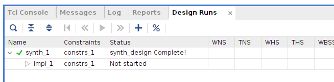
- 終了するとこの様にチェックマークが入ります。
- 画面の右の方に移動すると、かかった時間が表示されています。
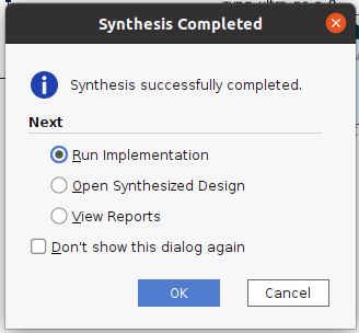
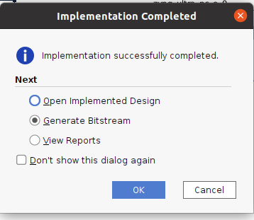
『Synthesis successfully completed』と表示されたので、続けて『Run Implementation』を選択して『OK』。次も『OK』
終了したら同様に
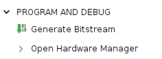
- 或いは、左側の『Flow Navigator』の下の『PROGRAM AND DEBUG』の『Generate Bitstream』を選択し、『OK』を押す。
- 『Launch runs on local host』のままで『OK』を押す。
- 実行経過が表示されないが、
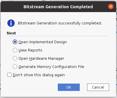
- 『Bitstream Generation Completed』のDialog Boxが表示されるまで待つ。(10分ほどかかる)
- 経過は、下のWindowの『Design Runs』タブを開くと、『Name』の下で『synth_1』の左側で緑の輪がぐるぐる回っているのがわかる。
『Launch runs on local host』で実行(*下の画像のメッセージは違います)
- 『Bitstream Generation Completed』のDialog Boxが表示されるまで待つ。(古いPCで10分ほどかかる、新しいPCで20秒)
- 経過は、下のWindowの『Design Runs』タブを開くと、『Name』の下で『synth_1』の左側で緑の輪がぐるぐる回っているのがわかる。
- 『Bitstream Generation Completed』のDialog Boxが表示されたら、結果をどの画面で見たいかを選択するだけなので、何を選択しても良い。 以下は初期値のまま。
また何故かWarningが出ましたがそのまま進みます。
左のメニューから『SYNTHESIS』〜『Open Synthesized Design』〜『Report Methodology』を実行して内容を見たけどよくわからず、そのまま次に進んだ。
TIMING #1 A primary clock ultra96v2_base_i/clk_wiz_0/inst/clk_in1 is created on an inappropriate pin ultra96v2_base_i/clk_wiz_0/inst/clk_in1. It is recommended to create a primary clock only on a proper clock source (input port or primitive output pin with no timing arc)
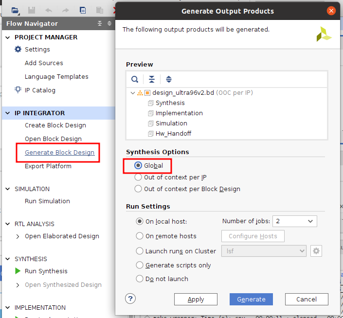
Generate Block Design(『Generate Output Products…』)
- Flow Navigatorから『Generate Block Design』を選び
- Synthesis Optionsで『Global』を選び
- 『Generate』
- もし『Out of Context Per IP』を選択して合成すると、Vivadoは各IPを合成するのでGlobalより時間がかかるそうです。
『OK』
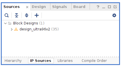
『IP Sources』タブを開くと生成されたことがわかります。
XSAファイル生成
XSAファイルはPetaLinuxやVitisを使うために用意します。
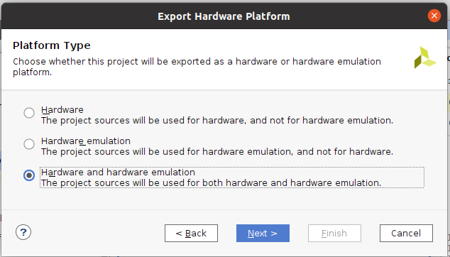
- 『File』→『Export』 → 『Export platform』を選択して『Next』
- 『Hardware』か『Hardware and hardware emulation』を選択して『Next』
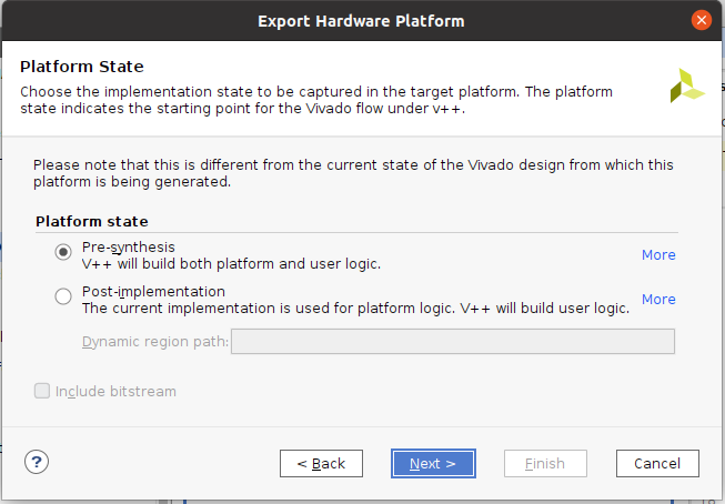
『Pre-synthesis』を選んで
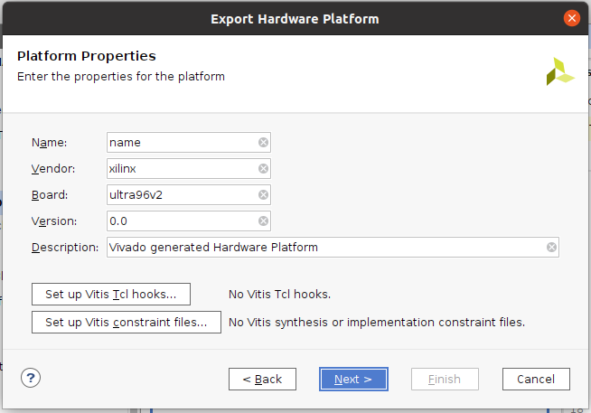
単にPropertyでこれらの文字列が入るだけなので、何もせず『Next』しました。
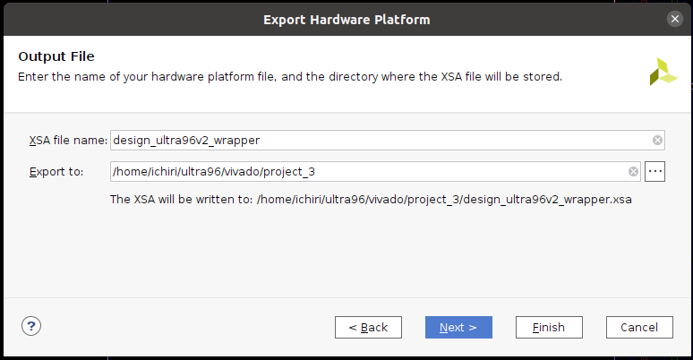
- xsaファイルと場所を指定して『Next』
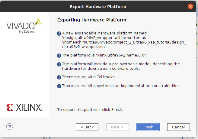
- 私は、何も変更せずにそのまま『Next』しました。(後から見てwrapperはちょっと無かったかなと思いましたが…) これで、『design_ultra96v2_wrapper.xsa』ファイルが生成されます。 今後このファイル名は何度も使うのでメモしておくといいと思います。
『Finish』
ファイルの確認
指定したディレクトリに、ちゃんとxsaファイルが出来ていますね。 次はこのxsaを使ってPetaLinuxで、Kernel、 rootfs、u-boot、sysrootを作ってみます。 (*2022.2では5MB弱だった.xsaが20MBになっていました。)
$ ls -l
total 19608
drwxrwxr-x 9 ichiri ichiri     4096  5月 23 11:36 .
drwxrwxr-x 3 ichiri ichiri     4096  5月 23 10:11 ..
-rw-rw-r-- 1 ichiri ichiri 20028197  5月 23 11:36 design_ultra96v2_wrapper.xsa
drwxrwxr-x 5 ichiri ichiri     4096  5月 23 11:36 project_3.cache
drwxrwxr-x 3 ichiri ichiri     4096  5月 23 11:04 project_3.gen
drwxrwxr-x 2 ichiri ichiri     4096  5月 23 10:14 project_3.hw
drwxrwxr-x 5 ichiri ichiri     4096  5月 23 11:12 project_3.ip_user_files
drwxrwxr-x 5 ichiri ichiri     4096  5月 23 11:21 project_3.runs
drwxrwxr-x 2 ichiri ichiri     4096  5月 23 10:14 project_3.sim
drwxrwxr-x 3 ichiri ichiri     4096  5月 23 10:15 project_3.srcs
-rw-rw-r-- 1 ichiri ichiri    12204  5月 23 11:36 project_3.xpr
次はPetaLinuxです。
おしまい
その他
参考
Vitis Tutorials: Vitis Platform Creation XD101 2022-11-07 2022.2
Vivado beremetal “Hello World” element14

PL部を使う時は、これを参考にしてみよう。

Vivado使い方をうまくまとめているサイト

Failed to load module “canberra-gtk-module”
Vivadoを起動してこのメッセージが出たら以下を実行
$ sudo apt install libcanberra-gtk3-module
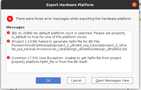
Export Hardware Platform時のエラー(ClockとReset接続)
このまま進んで『Export Hardware Platform』をすると、『is_default』が『true』になってないよとエラーが出てしまったので、色々調べてZynq UltraScale+ブロックのpl_clk_0とpl_resetn_0をつないだら、『Export Hardware Platform』できました。 これで本当にいいかどうか分っていません。 まあ、今回PL(FPGA部)は使っていないのでエラーがなかったらいいでしょう。
gitで管理する場合
以下の理由で、ファイルを生成するTclをgitで管理するのが最良。(データーベースのSQLを管理するみたいな)
- xpr(プロジェクトファイル)は関連するパス等が記述されていてディレクトリ構造が異なると使えなかったり、自動生成されて肥大化する為。
- bdは関連するディレクトリ等で100MBを超える為。
wifi
PetaLinuxで生成された、バイナリのsystem.dtbを文字列の.dtsファイルに変換して『wifi』で検索すると、以下の2箇所に書かれていました。 しかしこれだけでは十分でないのでWifiがアクティベートされないのでしょうね。 落ち着いて調べていこうと思います。
                        wifi@2 {
                                compatible = "ti,wl1831";
                                reg = <0x02>;
                                interrupt-parent = <0x11>;
                                interrupts = <0x4c 0x01>;
                                phandle = <0x79>;
                        };


// __symbols__ の下
wlcore = "/axi/mmc@ff170000/wifi@2";

コメント